
Most cable assembly suppliers build to print. Caton takes technical ownership of the high-voltage interface — from insulation system selection and electric field analysis through in-house testing and long-term manufacturing control.

Our dedicated engineering team works directly with system designers before production begins, because the decisions that determine high-voltage cable assembly performance are made during design — not on the production floor.
Engineering
Engineering philosophy

Technical ownership of the complete HV interconnect

50+
Years of high-voltage interconnect engineering — exclusively
We don't just build what you draw. We evaluate whether what you drew will perform — and stay stable — under real operating conditions over the life of your program.

Caton's engineering team is structured around high-voltage interconnect — not general electronics or connector manufacturing. Every engineer on our team works exclusively in this domain, which means the depth of knowledge our customers access is specific, practical, and directly applicable to the problems they are trying to solve.

We manufacture both the connector interface and the cable assembly. This matters because the highest-risk region in any high-voltage interconnect is the transition between the two — the termination region where conductor, insulation, and connector geometry meet. When those come from different suppliers, no one owns that interface. At Caton, one engineering team designs, builds, and takes technical responsibility for the complete interconnect.

What engineering-led manufacturing means in practice
When a customer releases a design with Caton, our engineering team doesn't hand it off to production and walk away. We remain technically responsible for that interface — evaluating any proposed changes, investigating field questions, and maintaining the design basis for as long as the program runs.
Engineering capabilities

What our engineering team can do for your program

Our engineering team brings dedicated high-voltage expertise to every stage of your program — from early design through production and field support.

  • Electric field analysis using Electro V10.2 — dedicated electrostatic field modeling at connector interfaces and termination regions, with molded geometry designed to control field stress, eliminate air gaps, and maintain continuous dielectric paths at mating interfaces
  • Insulation system design — material selection and architecture validated against voltage class, temperature range, altitude, chemical exposure, and long-term stability requirements
  • Corona and partial discharge evaluation — analysis of corona inception risk and partial discharge susceptibility in proposed designs before testing
  • Configuration control and change management — engineering review and disposition of any proposed changes after design release, maintained for the life of the program
  • Design-for-manufacturability review — evaluation of proposed designs for manufacturing feasibility, process control requirements, and long-term production consistency
  • System integration support — evaluation of the complete interconnect in the context of your system architecture, not just the cable assembly in isolation
  • Failure analysis — root cause investigation for field failures or qualification failures, with corrective action recommendations
  • Material compatibility assessment — evaluation of insulation and connector materials against chemical exposure, radiation, outgassing, and other environmental requirements
How we work

Engineering collaboration from requirements through production

Our engineering process is structured around the stages where high-voltage performance is determined — and where most problems are either prevented or created.

01
Requirements evaluation
Review of system voltage, current, environment, mechanical constraints, and program requirements. Platform selection and initial design direction established at this stage.
02
Design development
Insulation system selection, connector interface and termination geometry design, FEA modeling of electric field distribution, and design-for-manufacturability review.
03
Prototype and test
Prototype fabrication followed by in-house testing — corona, hi-pot, thermal, altitude, and environmental as required. Test results evaluated against design intent before production release.
04
Production and sustainment
AS9100-controlled production with locked configuration. Engineering team remains technically responsible for the design — reviewing any proposed changes and supporting field questions throughout the program lifecycle.
Test & validation capabilities

In-house testing that validates real performance — not just nominal ratings

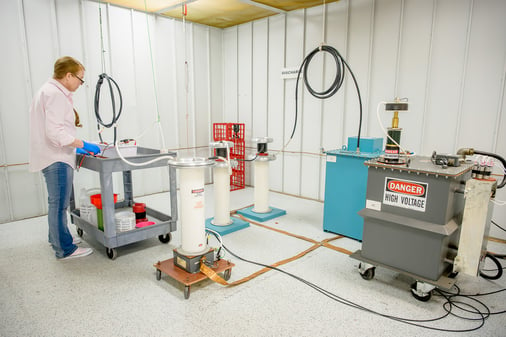
Caton maintains in-house test capabilities covering the most critical electrical, environmental, and life performance requirements for high-voltage cable assemblies. Testing requiring capabilities beyond our in-house equipment is performed at qualified external test houses.

 
Corona & Partial Discharge Testing
Four dedicated corona test cages for corona inception voltage and partial discharge measurement. Corona testing is performed on every design released for production and per program requirements.
IEEE 454 · In-house capability
 
Hi-Pot / Dielectric Withstand Testing
High-potential testing performed in-house to verify dielectric integrity of insulation systems and connector interfaces. Every production assembly receives hi-pot testing as part of standard build acceptance — not statistical sampling.
MIL-STD-202 Method 301 · 100% inspection
 
Altitude Simulation Testing
Tenny environmental chamber for altitude simulation testing. Reduced-pressure altitude testing verifies that electrical performance — particularly corona inception voltage — is maintained at the altitude conditions of the operating environment, including aerospace applications rated to 70,000 ft.
MIL-STD-810 Method 500 · To 70,000 ft
 
Thermal Cycling & Subzero Testing
Two dedicated subzero thermocycling machines for thermal cycling and low-temperature performance testing. Evaluates insulation system stability, connector interface integrity, and mechanical performance across the full operating temperature range — including -55°C rated assemblies.
MIL-STD-810 Method 503 · -55 to +125°C
 
Accelerated Life Testing
Accelerated life testing protocols to evaluate long-term insulation performance under elevated stress conditions. Used to validate insulation system stability and identify potential degradation mechanisms before they manifest in field applications.
In-house capability · Customer-specific protocols
 
Burn-In Testing
Burn-in testing under voltage and thermal stress to identify early-life failure modes before assemblies ship. Screens out infant mortality failures that would otherwise appear in the field during the early operational period of the program.
In-house capability · Program-specific parameters
 
Electric Field & Mechanical Modeling
Caton uses Electro V10.2 for dedicated electrostatic field analysis — computing electric field distribution at connector interfaces and termination regions during the design phase. Field modeling identifies concentration risks and validates insulation geometry before any hardware is built, reducing qualification risk and prototype iterations. Mechanical stress and deformation modeling is performed using Autodesk Inventor, with Inventor Nastran available for dedicated mechanical and thermal FEA.
Electro V10.2 · Autodesk Inventor · Design phase
 
First Article Inspection
Complete FAI packages per AS9102 including dimensional verification, material certifications, process records, and test data. FAI documentation is structured to support aerospace and defense program qualification requirements.
AS9102 · Full FAI package
Manufacturing discipline

Engineering accountability extends through production

Engineering capability means nothing if the manufacturing process doesn't execute the design with precision and consistency. At Caton, engineering and manufacturing are not separate functions — the same engineering discipline that designs the assembly governs how it is built.

Our AS9100-certified quality system provides the framework: documented standard work, qualified and trained personnel, controlled materials, and complete build records for every assembly. But the real discipline is the accountability that connects engineering intent to production output.

What this means for your program
The assembly that ships in year five of your program is built to the same engineering intent as the one that qualified in year one — because the engineering team that released the design is still accountable for every assembly that follows.
  • AS9100-certified quality management system
  • Documented standard work for all assembly and test operations
  • Qualified and trained personnel for high-voltage assembly processes
  • Controlled material sourcing with full certification traceability
  • 100% hi-pot testing on every production assembly
  • Complete build records — material certifications, process records, test data
  • Locked configurations with formal engineering change control
  • Configuration control maintained from first article through program end
  • ITAR-compliant facility and operations
  • NIST SP 800-171 and DFARS cybersecurity compliance
  • CMMC compliant

Ready to discuss your high-voltage engineering challenge?

Whether you are in early design, approaching qualification, or investigating a field performance issue — our engineering team can engage directly with your technical requirements.