
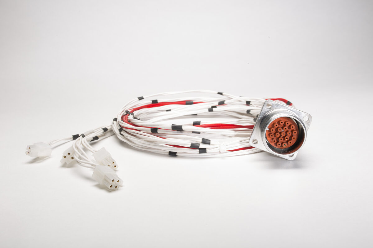
Partial discharge and corona are among the most consequential — and most misunderstood — long-term failure mechanisms in high-voltage interconnects. They often develop without external symptoms, can accelerate as insulation damage accumulates, and are usually preventable or detectable when the assembly is engineered and tested correctly from the start.
Topic: Corona & PD · 1 kV – 250 kV DC · Aerospace · Defense · Scientific · Industrial
What Corona and Partial Discharge Actually Are
The terms corona and partial discharge are frequently used interchangeably in field practice and in manufacturer literature. They are not the same phenomenon. Conflating them produces errors in both design and testing.
Partial discharge (PD) is the governing technical category. IEC 60270 — the international standard for PD measurement — treats it as a localized electrical discharge that only partially bridges the insulation between conductors. PD can occur in gases, liquids, and in defects or interfaces within solid insulation systems when local electric field stress exceeds the local dielectric strength. In practice, the relevant forms for high-voltage cable assemblies include internal PD (within voids or at interfaces inside solid insulation), surface PD (along insulation boundaries), and corona (in the surrounding gas).
Corona is a specific form of partial discharge that occurs in a gaseous medium — typically air — around a conductor remote from solid insulation. In IEC terminology, corona is not the general term for all partial discharge; it is a gas-discharge form of PD. In enclosed high-voltage connectors, the more consequential mechanisms are often internal PD and surface PD within or adjacent to the dielectric system — not open-air corona in the classical sense. The concern is what happens inside the dielectric system.
The characteristic appearance of corona — the faint blue-violet glow visible in darkness, the audible hiss, the ozone odor — are symptoms of ionization and recombination in the discharge region. They are not the failure mode. The failure mode is what those discharge events do to surrounding insulation over time.
The key danger
Corona and partial discharge do not cause immediate failure. They degrade insulation incrementally over thousands or millions of discharge events — often with no external indication until catastrophic breakdown occurs. A high-voltage cable assembly exhibiting PD activity at operating voltage should not be considered stable for long-term service, even if it passes initial electrical tests.
Important distinction
Corona and arcing are not the same phenomenon. Arcing is a full breakdown of the dielectric gap — a complete conducting path between conductors at different potentials. Corona is a localized discharge in a gas that does not complete that path. Corona can persist at operating voltage for extended periods without causing immediate system failure. Arcing is typically catastrophic and immediate. This distinction matters: a system with sustained corona or PD at operating voltage may not fail immediately, but it should be treated as a long-term reliability risk. The progression rate can be difficult to predict and depends on discharge magnitude, material system, environment, and duty cycle.
Where It Starts
Corona and partial discharge do not occur randomly across a cable assembly. They originate at specific physical locations where electric field stress is elevated — and those locations are predictable from the assembly geometry and construction method.
The most problematic locations in a typical high-voltage cable assembly are:
- The conductor-to-insulation interface at the termination point, where the cable shield is cut back and geometry transitions abruptly — creating a high-field region at the conductor surface
- Mating connector interfaces, where two separate components meet and air gaps are almost inevitable unless the geometry is specifically engineered to exclude them
- Internal voids in potted or encapsulated assemblies, formed during cure due to entrapped air, outgassing, or inadequate fill pressure — each void is a localized region of low dielectric strength within a higher-strength medium
- Any location where insulation materials are mechanically compressed rather than integrally molded — including taped constructions, heat-shrink terminations, and push-fit connector bodies — where air gaps and delaminations are structurally inherent
- Conductor surface irregularities: scratches, nicks, stranding features, and burrs at cut ends, where field enhancement at surface discontinuities raises local stress above the bulk-geometry calculation
Why Standard Assembly Practices Fail
Many cable assembly suppliers operate primarily as build-to-print manufacturers: they select insulation materials based on nominal dielectric strength ratings, assemble connectors according to mechanical fit, and rely on end-of-line electrical testing at the rated voltage before shipment. This approach is adequate for many lower-voltage applications but tends to fall short at higher voltage classes and in environments with altitude, temperature extremes, or long service life requirements.
Air at mating interfaces is treated as acceptable
Many connector designs rely on mechanical compression at mating surfaces to minimize air at the interface — but compression contact is not the same as dielectric continuity. In conventional flat-face or butt-contact geometries, the interface contains air. In compact high-voltage geometries, especially as operating voltage rises into the 10 kV class and above, persistent air films under mechanical compression become corona or PD initiation sites if field stress is not controlled. The problem is structural — not a manufacturing defect that tighter assembly tolerances will resolve.
The altitude problem
Corona inception voltage decreases as ambient pressure decreases, over the pressure range relevant to most aerospace applications. This behavior is governed by Paschen's Law, which describes breakdown voltage in a gas as a function of the product of pressure and electrode gap length (the pd product) — not pressure alone. The threshold also depends on gas composition, electrode geometry, and surface condition. As pressure drops from sea level toward typical unpressurized aircraft operating altitudes, breakdown voltage for a given small gap decreases substantially, reducing or eliminating the margin that was present at ground level. Under a standard-atmosphere model, ambient pressure at 70,000 ft is approximately 4–5% of sea-level pressure — roughly 5 kPa versus 101.3 kPa at sea level. In this pressure range, reduced pressure can substantially lower the voltage required to initiate discharge in small gaps.
It is important to note that Paschen's curve is not monotonic. At very low pressures approaching hard vacuum, breakdown voltage rises again. The critical regime for most aerospace hardware — unpressurized bays, depressurized compartments, high-altitude operation — falls on the descending portion of the curve, where reduced pressure is the dominant risk. Ground-level acceptance testing does not verify adequate corona margin in this regime. Qualification at simulated altitude conditions is required to establish a valid margin. (Paschen, F., Annalen der Physik, 1889; NASA-HDBK-4007)
The surface tracking problem
Partial discharge — particularly at or near insulation surfaces — generates ozone, nitrogen oxides, and other chemically active species as byproducts of the ionization process. In carbon-containing polymer insulation systems, these byproducts attack the surface and initiate a degradation process that can produce electrically conductive paths along or through the insulation — a phenomenon called tracking. In some materials these paths become carbonized; in others the mechanism is primarily erosion and acid attack driven by nitric acid formed when nitrogen oxides combine with moisture. The chemistry varies by material, but the consequence is consistent from a system standpoint: the insulation surface becomes more conductive or more easily discharged, local field stress increases at the degraded region, and the process can accelerate toward flashover or breakdown. (IEC 60270:2000, Annex F; Gorur, R.S. et al., 1999)
Engineering note
Tracking is self-reinforcing. The degradation that begins with corona creates the conditions for progressively more severe discharge. A connector that was functioning adequately may degrade rapidly after a tracking path initiates — particularly at elevated temperature or after mechanical disturbance of the interface. This is not a gradual linear process; it is a positive feedback mechanism with an inflection point.
The inspection problem
Partial discharge is invisible to standard visual inspection and most continuity or resistance tests. Low-level corona can persist for months or years before causing measurable degradation, and may not be detected by a production hi-pot test if the discharge magnitude is below the test setup's detection threshold. This means assemblies that pass standard acceptance testing may have an active PD failure mechanism operating below the test sensitivity floor — and ship with it.
Potting is applied at atmospheric pressure
Standard potting practice is to dispense material at atmospheric pressure and allow it to cure in place. Air entrained during mixing and flow into confined geometry does not reliably escape before the material gels. The result can be a cured potting mass with entrapped air or interfacial microvoids — particularly in blind cavities, undercuts, conductor bundles, or abrupt geometry changes. These defects may be invisible to visual inspection and dimensional checks, yet become PD initiation sites at sufficient field stress.
How the Geometry and Physics Drive the Outcome
The distribution of electric field in a connector interface is determined almost entirely by geometry. The permittivity of surrounding materials shifts the field distribution, but the geometry — conductor radius, insulation thickness, interface angles, void locations — determines where field concentration occurs and to what magnitude.
At Caton, we analyze electric field distribution using Electro V10.2 electrostatic field modeling software before applicable new high-voltage designs are released to tooling. This allows us to identify high-field regions, evaluate the effect of geometry changes, and compare predicted field stress against material and gas-discharge design limits across the operating voltage range — including at altitude-equivalent conditions for applicable programs. Final corona / PD margin is then verified by test under defined voltage, pressure, and fixture conditions.
The output of this analysis is not a calculation that confirms the design is adequate. It is a map of where the field concentrates and by how much — which drives design decisions before any physical hardware exists.
Engineering note — corona inception voltage
Corona inception voltage (CIV) is the voltage at which corona activity first becomes detectable in a test specimen under defined test conditions. CIV is not a fixed property of an assembly — it depends on test method, electrode geometry, ambient conditions, and ambient pressure. For assemblies rated for altitude operation, sea-level CIV measurements must be interpreted in the context of the Paschen relationship for the specific gas-gap geometry present in the assembly. A CIV margin that appears adequate at sea level may be inadequate at the rated operating altitude.
How Caton Addresses It — Engineering controls for corona and PD risk
- Electrostatic field modeling before tooling. Applicable new high-voltage designs are evaluated using Electro V10.2 field modeling before tooling is released. Field stress is mapped at conductor surfaces, material interfaces, and the mating region. Concentration points are identified and resolved through geometry changes. Designs proceed to production when predicted field stress falls within material and gas-discharge design limits — with margin — at all points in the assembly, including altitude-equivalent conditions where applicable. Final corona / PD margin is verified by test.
- Molded geometry that reduces air-gap risk at the interface. In-house overmolding and insert molding create a controlled, molded dielectric path at the most electrically critical locations — the connector interface and cable termination. Compared with mechanically assembled insulation systems, this approach substantially reduces air-gap and delamination risk when the material system, surface preparation, and molding process controls are validated.
- Tapered mating geometry that actively excludes air. Where connectors mate, the interface is designed with a tapered conical geometry that displaces air from the interface as the connection is made — rather than relying on compression of mating surfaces against a trapped air film. The design objective is a continuous solid dielectric path through the mated connector, with no uncontrolled air-filled region in a high-field area. Corona-free performance at operating voltage is then verified by production or qualification testing under defined conditions.
- Controlled conductor surface preparation. Conductor surface finish at high-field regions is treated as an engineering requirement, not a workmanship standard. Preparation requirements are specified and verified — not left to technician judgment — because surface irregularities are a predictable source of field enhancement and a first-order variable in corona inception voltage.
- 100% corona / PD testing on applicable high-voltage production assemblies — no sampling. Caton operates four in-house corona test cages. Every applicable high-voltage production assembly is tested for corona inception voltage (CIV) before shipment — not statistically sampled, not lot-tested. CIV is measured against the acceptance criterion for the assembly; units that fail to meet the required margin are rejected and investigated before any further units ship. The test result that matters is the one for the specific assembly you receive.
- Altitude chamber qualification for aerospace programs. For assemblies destined for aerospace applications, Caton qualifies corona performance in a Tenny altitude chamber at simulated reduced pressures corresponding to the rated operating altitude. Ground-level acceptance testing alone is not considered sufficient evidence of adequate corona margin for altitude-rated programs. The Paschen relationship is verified against hardware, not assumed from sea-level data.
What to Ask Your Current or Prospective Supplier
The following questions help distinguish suppliers with high-voltage engineering capability from suppliers that primarily build to print. They should be answered with design rationale, process controls, and test evidence — not only catalog ratings or generic workmanship language. A supplier that cannot answer them with specific engineering substance may not have the depth required for high-reliability high-voltage applications.
- What method do you use to analyze electric field distribution in the connector design — and can you show us the results? A supplier who models field distribution can show where stress is highest and what margin exists above corona inception thresholds. A supplier who does not model cannot make that case analytically — only empirically, by testing hardware after the fact.
- Is the connector interface molded or mechanically assembled? What provisions prevent air entrapment at the mating surface? This is an architecture question. Mechanical assembly tends to create discrete dielectric interfaces; molding can reduce uncontrolled air gaps and produce a more controlled dielectric transition when material bonding and process controls are validated. Compression contact alone is not a sufficient answer for high-voltage applications in the 10 kV class and above at altitude. Ask for the specific mechanism.
- Do you perform corona testing on every assembly, or do you sample test? What is your test sensitivity — the lowest detectable discharge magnitude? Sampling plans manage lot risk, not individual assembly risk. The question is whether the specific assembly you are receiving has been tested and accepted — not whether the lot it came from was statistically adequate. Test sensitivity matters because a PD level below the floor of a low-sensitivity tester is not the same as no PD.
- Have you qualified this assembly at altitude? What was the corona-free voltage margin at the test pressure? For assemblies that will operate at altitude, sea-level corona test results alone are not sufficient evidence of adequate performance. Ask specifically about reduced-pressure testing — what altitude was simulated, what chamber was used, and what margin was demonstrated.
- If we bring you a field failure, can you evaluate it for partial discharge damage and trace the failure mechanism back to a root cause? This reveals whether the supplier has engineering depth or is a pure production operation. A supplier with no PD analysis capability cannot distinguish a corona-initiated failure from a dielectric strength failure — which means they cannot close the loop on root cause and prevent recurrence.
- What are your conductor surface preparation requirements for high-field regions, and how are they verified? If the answer relies only on generic workmanship standards or visual inspection, surface finish may not be controlled as a high-field design variable. Ask for the requirement value and the verification method.
Technical References
- IEC 60270:2000 (with AMD1:2015) — High-Voltage Test Techniques: Partial Discharge Measurements. International Electrotechnical Commission. The international standard covering measurement methodology and test circuit requirements for partial discharge. Provides the technical framework for the PD and corona definitions and degradation mechanisms referenced throughout this note.
- Paschen, F. (1889) — "Über die zum Funkenübergang in Luft, Wasserstoff und Kohlensäure bei verschiedenen Drucken erforderliche Potentialdifferenz." Annalen der Physik, 273(5), pp. 69–96. Original empirical work establishing the pressure-gap-breakdown voltage relationship for gases, forming the basis of Paschen's Law and the Paschen curve referenced in the altitude discussion.
- NASA-HDBK-4007A — Spacecraft High-Voltage Paschen and Corona Design Handbook. NASA, current revision. Practical engineering reference for corona onset, Paschen behavior, and high-voltage design across the full pressure range from sea level through deep vacuum. Directly relevant to reduced-pressure high-voltage design for aerospace and space hardware; aircraft cable assembly design should also account for application-specific environmental conditions.
- Gorur, R.S., Cherney, E.A., and Burnham, J.T. (1999) — Outdoor Insulators. Phoenix, AZ: Ravi S. Gorur Inc. Technical reference for tracking mechanisms in polymeric insulation systems, including the role of corona byproducts — ozone, nitrogen oxides, nitric acid — in initiating and accelerating surface degradation. Referenced in the tracking discussion in Section 3.
- Dissado, L.A. and Fothergill, J.C. (1992) — Electrical Degradation and Breakdown in Polymers. IET/Peter Peregrinus, London. Comprehensive reference on the mechanisms by which partial discharge degrades polymer insulation systems over time. Supports the progressive degradation and positive-feedback mechanism discussion throughout.
References are provided to support the technical claims in this application note and to allow engineers to verify source material independently. Where IEC standards are cited, the edition current at the time of publication applies. Contact our engineering team if you have questions about how any of these references apply to a specific application or voltage class.