
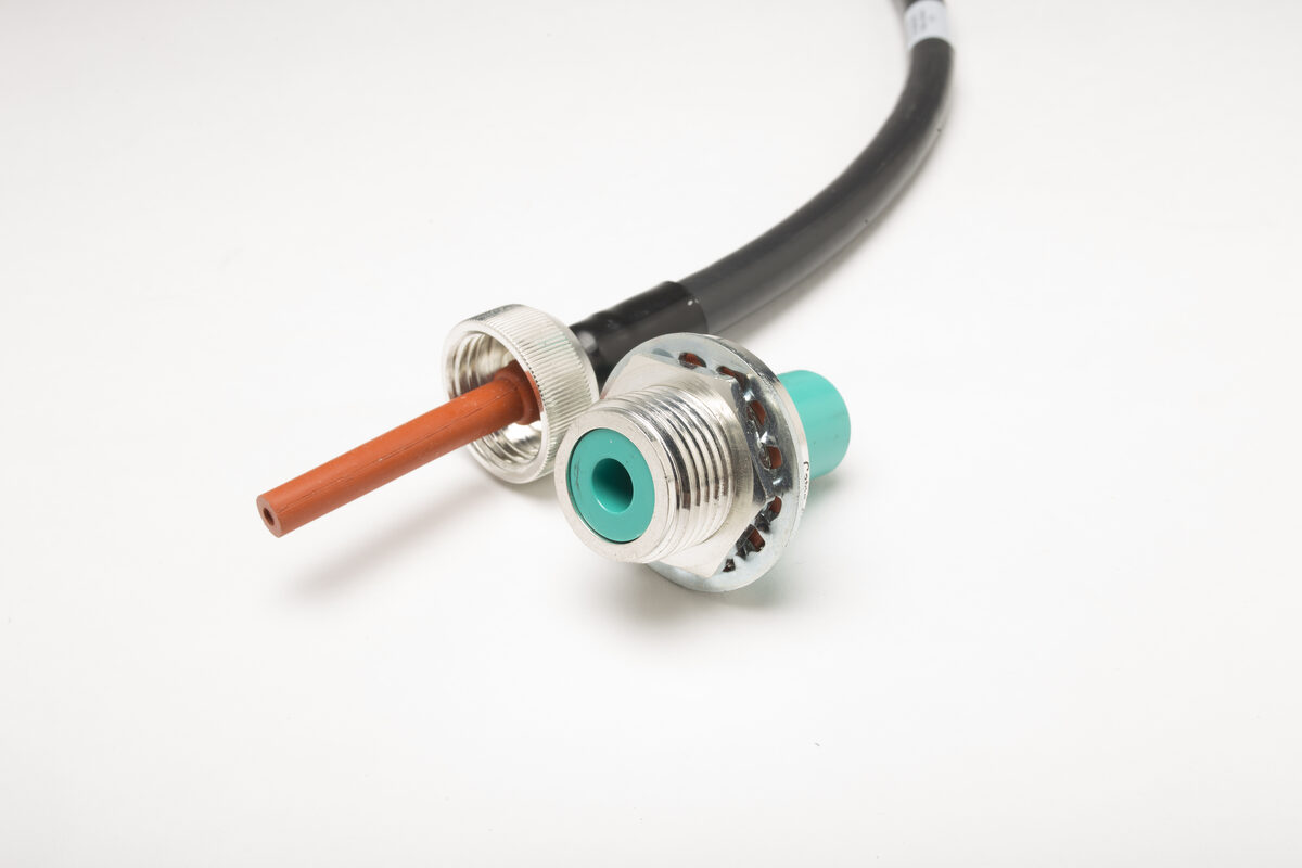
Insulation system selection is an architecture decision — not a materials lookup. The wrong choice, or the right material improperly applied, produces assemblies that pass incoming inspection and fail in service. The mechanisms that drive these failures are well understood, and they can usually be prevented or detected when the design process accounts for the full operating environment from the start.
Insulation System Design · 10 kV – 250 kV DC · Aerospace · Defense · Medical · Scientific
What an Insulation System Actually Is
In everyday procurement language, "insulation" usually refers to the dielectric jacket on the conductor. In high-voltage cable assembly design, the insulation system is the entire architecture — primary conductor insulation, any shield or screen layers, the termination insulation structure, the connector body dielectric, and every material interface between them.
This distinction matters because in well-manufactured high-voltage cable assemblies, the limiting risk is often not the bulk of the primary insulation. It is at the interfaces: where cable insulation meets connector body insulation, where the conductive shield is cut back, where overmold meets jacket, or where a potting compound contacts the insulation surface. Each of these boundaries is a discontinuity in material properties, and discontinuities concentrate the electric field.
Selecting an insulation system means designing this complete architecture — not selecting a material from a datasheet and applying it without regard to what it is adjacent to. A silicone rubber insulation system with well-characterized bulk dielectric strength can still fail at an interface if the adjacent connector body material has a significantly different relative permittivity, and that mismatch was not accounted for in the field analysis.
Key Term — Relative Permittivity
Relative permittivity (also called dielectric constant, symbol εr) describes how a material responds to an electric field relative to a vacuum. At a boundary between two materials with different permittivities, the normal component of electric field changes according to the permittivity ratio — the lower-permittivity material can experience higher field stress, depending on interface orientation and geometry. For silicone rubber (εr ≈ 2.8–3.5), PTFE (εr ≈ 2.0–2.1), and ETFE (εr ≈ 2.6), the differences appear modest in isolation. At high voltage, even modest permittivity mismatches at a poorly designed interface — or at a void — can concentrate enough field stress to initiate partial discharge. IEC 62631-2-1 describes standardized measurement methods for permittivity of solid insulating materials.
Primary Insulation Materials — What the Specifications Distinguish and What They Don't
The four materials most commonly encountered in high-voltage cable assembly insulation for demanding applications are silicone rubber, PTFE, ETFE, and cross-linked polyethylene (XLPE). Each has genuine strengths and specific failure modes that the specifications do not always make obvious.
Silicone rubber
Silicone rubber (often specified to A-A-59588 or SAE AS22759 for wire) is a common choice in many high-voltage cable assemblies for aerospace, defense, and scientific applications. Its combination of wide temperature range, corona / ozone resistance (formulation-dependent), flexibility at cryogenic temperatures, and processability for overmolding makes it suitable across a broad range of conditions.
The dielectric strength of silicone rubber — typically 18–25 kV/mm under short-time testing per ASTM D149 / IEC 60243 — is sufficient for the voltage classes encountered in these applications when geometry is correctly controlled. What silicone rubber does not offer is high abrasion resistance or cut-through resistance, and it is attacked by concentrated acids, strong bases, and some chlorinated solvents. Chemical compatibility must be evaluated for the specific compound and the specific chemicals present, not assumed from generic silicone data.
An important distinction: A-A-59588 is a commercial item description that specifies minimum electrical, mechanical, and thermal performance. It does not lock the formulation. Two suppliers' A-A-59588 compounds may have different dielectric strength values, different temperature indices, and different corona resistance behavior. For critical applications, the specific compound should be identified and locked at qualification.
PTFE
PTFE offers one of the lowest relative permittivities among common solid cable insulation materials (εr ≈ 2.0–2.1) and one of the widest continuous service temperature ranges (rated to 260°C in some constructions). These properties make it the insulation of choice for applications where elevated temperature and signal integrity are both critical — most commonly in aerospace and defense wire per MIL-DTL-22759.
PTFE's limitation for high-voltage connector applications is processability. It cannot be conventionally melt-extruded or injection-molded due to its exceptionally high melt viscosity; it must be ram-extruded, paste-extruded, or tape-wrapped and then sintered. This manufacturing constraint means it is most commonly used as wire insulation rather than as a molded connector-body or termination insulation material in complex geometries.
ETFE
ETFE (ethylene tetrafluoroethylene) is the most common fluoropolymer alternative when PTFE's processing constraints are prohibitive. It can be conventionally extruded, offers good dielectric strength and chemical resistance, and is typically rated for continuous service to approximately 150°C depending on construction. Its permittivity (εr ≈ 2.6) is higher than PTFE but lower than silicone rubber, which makes it a useful intermediate option when both temperature and field distribution need to be managed.
XLPE
Cross-linked polyethylene is the dominant insulation for medium- and high-voltage power cables per IEC 60502 (up to 30 kV) and IEC 60840 (above 30 kV). It offers high dielectric strength (typically ≥20 kV/mm), low dielectric loss, and excellent resistance to water tree aging. Its limitation for the connector applications discussed in this note is flexibility and operating temperature — rated to 90°C conductor temperature in standard constructions, with reduced flexibility at low temperatures compared to silicone rubber. XLPE is widely used in power cable insulation but is rarely the preferred material for compact connector-body or custom termination insulation in the applications discussed here.
| Material | Temp. Range (typical) | Dielectric Strength | εr (approx.) | Key Limitation |
|---|---|---|---|---|
| Silicone Rubber | −55°C to +200°C | 18–25 kV/mm | 2.8–3.5 | Low abrasion resistance; chemical attack by concentrated acids/bases |
| PTFE | −65°C to +260°C | 19–24 kV/mm | 2.0–2.1 | Cannot be injection-molded; most commonly used as wire insulation rather than as molded connector body |
| ETFE | −65°C to +150°C | 18–24 kV/mm | 2.6 | Higher cost than silicone; less flexible than silicone, especially in thicker-wall constructions or at low temperature |
| XLPE | −40°C to +90°C (conductor) | ≥20 kV/mm | 2.3 | Reduced flexibility at low temp; not suited for connector body use |
Typical property ranges — not design values. Dielectric strength values reflect short-time testing per ASTM D149 / IEC 60243 in approximately 1–3 mm specimens. Final design values must be based on the specific compound, construction, supplier data, test method, wall thickness, geometry, temperature, waveform, aging condition, and qualification results.
Where Standard Practice Falls Short
Specifying the material without specifying the system
The most common procurement error in high-voltage cable assembly specification is to define the cable insulation material and the connector type, and leave the transition between them — the termination insulation architecture — to the manufacturer's discretion. For applications below a few kilovolts, this is inconsequential. Above 10 kV DC, the termination region is where the field distribution changes most rapidly, and the insulation architecture at the termination determines whether the assembly works or fails.
A manufacturer without high-voltage engineering experience will apply the same insulation material to the termination that is used on the cable body, without analyzing the field distribution at material interfaces or at geometric transitions. The resulting assembly may pass a hi-pot screen and still exhibit partial discharge at operating voltage — because the failure mode is a localized field concentration, not a bulk insulation failure, and hi-pot testing does not detect incipient partial discharge.
Treating bulk material properties as design values
Dielectric strength data from material datasheets reflects short-time testing of a planar specimen — a standard geometry with uniform field, without the geometric complexities of a real termination. The design value for insulation in a high-voltage connector or termination must account for the actual field distribution, which depends on the geometry, and for the long-term operating conditions, which degrade dielectric performance over time.
The ratio of bulk material dielectric strength to the maximum field intensity in the actual design geometry — the design margin — should be explicitly calculated, not assumed. A material with a 20 kV/mm dielectric strength does not provide a design margin of 20 against a 1 kV/mm average field stress, because field concentration at geometric features can raise local field intensity well above the average.
Ignoring conductor temperature when sizing insulation
The operating temperature of the insulation in a current-carrying cable is not the ambient temperature of the installation — it is the temperature at the outer surface of the conductor, which includes the heat generated by resistive losses (I²R) in the conductor. In thermally constrained installations (enclosed conduit, bundled cables, minimal airflow), the conductor can run significantly hotter than ambient. The insulation must be evaluated at the conductor surface temperature, not at the ambient environment temperature.
Thermal Aging — The 10°C Rule
A common rule of thumb derived from Arrhenius aging behavior — formalized in IEC 60216 (thermal endurance) and referenced in IEEE Std 98 — is that thermal aging rate often increases substantially for each 10°C increase in operating temperature, frequently approximated as doubling. Using this rule of thumb, continuous operation 20°C above the intended thermal rating could reduce service life by roughly a factor of four. The actual acceleration factor depends on activation energy, material system, failure criterion, and oxygen availability — and should be based on thermal endurance data where life is critical. The conductor temperature under full load in the actual installation must be calculated and compared to the insulation thermal index before the material is selected.
Ignoring permittivity mismatch at material interfaces
At a boundary between two solid insulating materials, the normal component of the electric displacement field D is continuous, but the field intensity E is not. If material A has permittivity εA and material B has permittivity εB, the field intensity ratio at a planar interface is εA/εB. The lower-permittivity material experiences the higher field intensity.
In a simplified planar normal-field case, a silicone rubber insulation system (εr ≈ 3.0) adjacent to an air void (εr = 1.0) can place substantially higher field stress in the air than in the adjacent silicone — by roughly the permittivity ratio in this idealized case. In real geometries, the exact stress enhancement depends on void shape, orientation, size, location, and the surrounding field distribution. This is why even small voids at material interfaces — not detectable visually, not detectable by dimensional inspection — can become partial discharge sites at elevated voltage. The design objective is to avoid uncontrolled gas-filled regions at interfaces in the high-field path, not simply to avoid visible gaps.
How Material and Geometry Together Determine Dielectric Performance
Dielectric performance in a high-voltage cable assembly cannot be determined from material properties alone. The field distribution is a function of geometry — conductor diameter, insulation thickness, the shape of the termination transition, the proximity of grounded surfaces — and of the permittivities of all materials in the field path.
For a simple coaxial geometry, the field distribution is calculable analytically. For the three-dimensional, multi-material geometry of a high-voltage connector or termination, it is not — numerical field analysis is the appropriate tool. Caton performs electrostatic field modeling using Electro V10.2 before applicable new high-voltage designs are released to tooling. The analysis predicts field intensity at modeled material interfaces and geometric transitions, identifies high-stress regions, and estimates design margin before hardware is built. Final margin is verified by electrical and environmental testing.
For compact, high-reliability high-voltage assemblies, field analysis should be treated as a required design activity, not an optional refinement. The combination of correct material selection and correct field analysis is what produces an insulation system that performs at rated voltage. Material selection without field analysis produces an insulation system that may or may not perform, with no analytical basis for predicting which.
Engineering Note — DC Field Distribution
Under AC excitation, field distribution in an insulation system is governed by relative permittivity. Under DC excitation, steady-state field distribution is governed by volume resistivity — and the two distributions can be significantly different for the same geometry and materials. In real DC systems, neither the pure capacitive (permittivity-governed) nor the pure resistive (resistivity-governed) distribution applies at all times: the transition between them depends on the RC time constant of the insulation system. For DC applications above 10 kV, field analysis must address both distributions across the operating temperature range, because volume resistivity is strongly temperature-dependent in most polymer insulation materials.
Altitude and the Insulation System
The dielectric strength of solid insulation materials is not significantly affected by ambient pressure. Silicone rubber, PTFE, and ETFE do not exhibit Paschen-curve behavior — the breakdown of solid insulation is not pressure-dependent in the way that gas breakdown is.
The altitude sensitivity of an insulation system usually lies in trapped or exposed gas: air at material interfaces, potting voids, mating connector gaps, or external high-field regions. At reduced pressure, these gas-filled regions may experience lower corona / PD inception voltage according to Paschen-type behavior. The relationship is nonlinear and depends on the pressure-gap product, gas condition, geometry, and local field distribution. Under a standard-atmosphere model, ambient pressure at 70,000 ft is approximately 4–5% of sea-level pressure. A void that contributes negligibly to corona / PD behavior at sea level may become an active discharge site at altitude.
The correct design objective for airborne high-voltage assemblies is to avoid air-filled voids and uncontrolled air gaps in electrically stressed regions — at interfaces, through transitions, and at any location experiencing elevated field stress. This is more reliably achieved through overmolded insulation structures with geometrically controlled interfaces and vacuum-applied potting for multi-conductor transitions. Atmospheric potting is difficult to validate as void-free in complex high-voltage geometries, even with good workmanship; vacuum potting or molded insulation provides higher process control where void-related PD risk is unacceptable. Process controls and altitude corona / PD testing should then verify adequate margin under the relevant pressure conditions.
How Caton Addresses It — Engineering Controls for Insulation System Integrity
- Field analysis before material finalization. Caton uses Electro V10.2 electrostatic field modeling to evaluate field distribution in the complete insulation system geometry — including all material interfaces and transitions — before material selection is finalized and before any tooling is committed. The analysis identifies field concentration points that would not be visible in dimensional inspection and confirms that design margins are adequate at every location in the field path.
- Overmolded termination insulation — geometry controlled by tooling, not by hand. For single-conductor high-voltage assemblies, the termination insulation can be formed by injection molding rather than hand-applied potting. Molded tooling controls the insulation geometry reproducibly, and pressure-assisted fill substantially reduces void risk compared with atmospheric-applied materials. The result is a controlled dielectric transition from cable insulation through connector body, with reduced risk of interfacial gaps or delamination under thermal cycling or mechanical loading when the material system, surface preparation, and process controls are validated.
- Vacuum potting for multi-conductor terminations. Where potting is required — multi-conductor configurations, backshell fills — Caton applies the compound under vacuum. The termination cavity is evacuated before potting material is introduced. When the vacuum is released, atmospheric pressure drives the compound uniformly into all cavities and against all surfaces. This directly addresses void formation in the geometrically complex regions of multi-conductor terminations, where atmospheric potting is difficult to validate as void-free.
- 100% corona inception testing on applicable high-voltage production assemblies. Every applicable high-voltage production assembly is tested for corona inception voltage (CIV) in one of Caton's four production corona test cages. The test ramps to measured CIV and verifies adequate margin above the rated operating voltage — confirming that the complete insulation system, as built, has no partial discharge activity below the acceptance threshold. This is the most direct production electrical screen for insulation-system defects that create discharge activity, including voids, interface gaps, and unmanaged field concentration. Hi-pot testing is performed separately as a complementary withstand screen.
- Altitude qualification for airborne applications. Assemblies intended for airborne or altitude-sensitive applications are tested in Caton's Tenny altitude chamber at the ambient pressure corresponding to the application's operational altitude. Altitude testing verifies that no partial discharge activity is introduced at reduced pressure in locations that are electrically inactive at sea level. This is the most direct way to verify reduced-pressure discharge margin for an airborne application — used together with field analysis, process controls, and qualification testing appropriate to the service environment, because the location of any residual air in the insulation system cannot be assumed.
What to Ask Your Current or Prospective Supplier
These questions help distinguish suppliers who design insulation systems from suppliers who select materials from a datasheet. A technically capable supplier should be able to answer each of these with design rationale, process controls, and test evidence — not only the material supplier's published specifications.
- Have you modeled the electric field distribution in the complete insulation system — including all material interfaces and the termination transition geometry — for this application? Can you show us the field plots and your design margin at the highest-stressed location?
- What is the conductor temperature under full-load conditions in our installation, and how does that compare to the thermal index of the insulation material you are proposing? Have you confirmed this with thermal analysis or test?
- How is the termination insulation applied — overmolded, vacuum-potted, or atmospheric-potted? What process controls and test evidence support void control at the cable-to-connector interface in the finished assembly?
- What is the relative permittivity of each material in the dielectric path, and where is the largest permittivity step change? Have you analyzed the field concentration at that interface?
- Do you perform corona / partial discharge inception voltage testing on production assemblies? Is this 100% of units or a sample? What is your PDIV acceptance threshold relative to the rated operating voltage?
- Has this insulation system been qualified at altitude — or at the reduced pressure corresponding to our application environment? Do you have in-house altitude test capability?
Technical References
- IEC 60216-1:2013. Electrical insulating materials — Thermal endurance properties — Part 1: Ageing procedures and evaluation of test results. IEC, 2013. Establishes the Arrhenius-based framework for characterizing thermal endurance of insulating materials and defines the Temperature Index concept. Foundational to the thermal aging discussion in this note and directly relevant to insulation material selection for high-temperature applications.
- ASTM D149-20. Standard Test Method for Dielectric Breakdown Voltage and Dielectric Strength of Solid Electrical Insulating Materials at Commercial Power Frequencies. ASTM International, 2020. Aligned with IEC 60243-1. Defines the test geometry, conditioning, and voltage application procedures used to generate dielectric strength data reported in material datasheets. Essential context for interpreting and appropriately de-rating published dielectric strength values for design use.
- IEC 62631-2-1:2018. Dielectric and resistive properties of solid insulating materials — Part 2-1: Relative permittivity and dissipation factor — Technical frequencies (0.1 Hz to 10 MHz) — AC methods. IEC, 2018. Defines standardized measurement methods for permittivity of solid insulating materials. Directly applicable to the permittivity mismatch discussion in this note and to the characterization of insulation materials for use in multi-material field analysis.
- Eoll, C.K. (1975). "Theory of stress distribution in insulation of high-voltage DC cables." IEEE Transactions on Electrical Insulation, EI-10(1), 27–35. The foundational paper establishing that DC field distribution is resistivity-governed rather than permittivity-governed in steady state — and that the transition between the two distributions is determined by the RC time constant of the insulation system. Directly relevant to DC high-voltage insulation system design; commonly overlooked in practice adapted from AC cable standards.
- IEEE Std 98-2016. IEEE Standard for the Preparation of Test Procedures for the Thermal Evaluation of Solid Electrical Insulating Materials. IEEE, 2016 (supersedes IEEE Std 98-2002). Establishes principles for the development of test procedures to evaluate thermal endurance of solid electrical insulating materials in air, based on the Arrhenius model. Sets the standard test basis for thermal endurance claims used in insulation material qualification for high-reliability applications.
References are provided to support the technical claims in this application note and to allow engineers to verify source material independently. Where standards are cited, the edition current at time of publication applies. Contact our engineering team with questions about how any reference applies to a specific application.